Fire Hydrant Valve Assembly
Breaking Down Components Of A Fire Hydrant

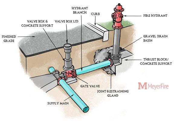
Fire Hydrant System Diagram Fire Hydrant System Fire Systems Fire Sprinkler System

Fire Hydrant Colors Their Nfpa Spectrum And Meaning

Metropolitan M 94 U S Pipe Valve Hydrant Llc
Brooks Emergency Response Products Hose Valves Hydrant Valves

Fire Hydrant 1650x2550 Drawing With Labels And Functional Descriptions Thingscutinhalfporn
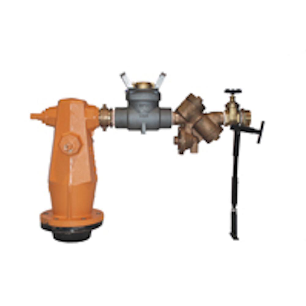
Assemblies booster hydrant booster and hydrant assemblies consist of arrangements of valves pipe work to suit specific site fire protection needs.
Fire hydrant valve assembly.
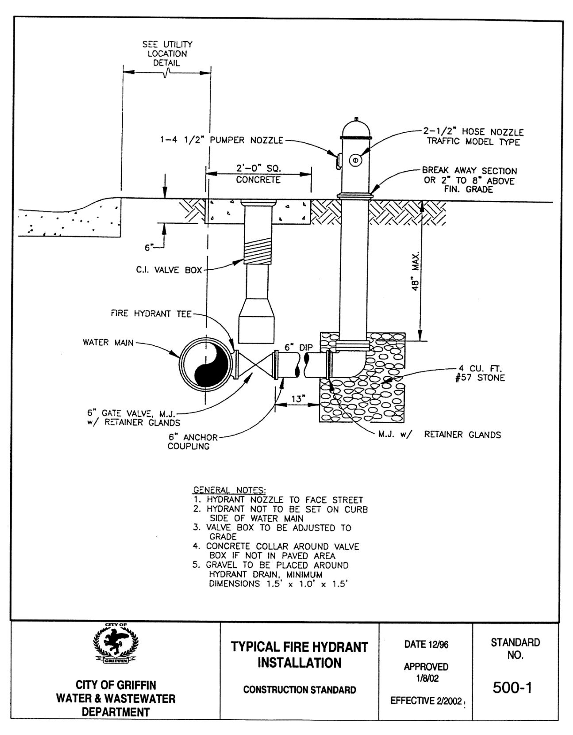
Article 15 Fire Safety Systems Code Of Ordinances Griffin Ga Municode Library
Http Mh Valve Com Upl Downloads Resources Product Brochures Model 129 Fire Hydrant Pdf
Https Www Jstor Org Stable 41252933

Animation Of Avk Dry Barrel Fire Hydrant Youtube
Source : pinterest.com
